FM Telephone Transmitter
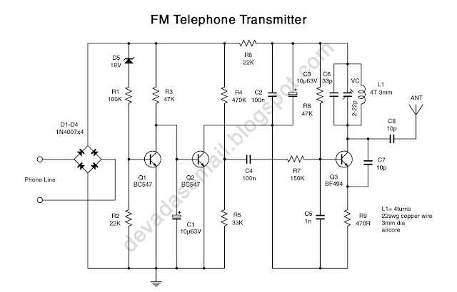
The complete schematic of the telephone bug is shown in Fig.1. This circuit connects in parallel with the telephone line. Power for the circuit is full wave bridge rectified from the phone line by diodes D1 through D4. When the telephone receiver is on hook the voltage across the lines will be about 48 volts. At this voltage the Zener diode D5 will be in breakdown and the transistor Q1 will conduct. This makes the transistor Q2 OFF. When the receiver is off hook, the line voltage drops to about 12 volts. This makes the transistor Q1 OFF and subsequently the Q2 ON. The Q2 in switched ON condition will provide a DC path for the transistor Q3 in the FM transmitter section. The transmitter section is actually a small FM transmitter that can be turned to a vacant spot on your Fm radio. In the FM frequency range, only a small antenna is needed to radiate a usable signal through out a building. Its range is 50 to 100 feet with a 10cm antenna. The range can be increased by using a longer antenna. Transistor Q3 oscillate at a signal frequency which is determined by turned circuit L1, C6, VC and the inter electrode capacitance of the transistor. Capacitor C7 provides the needed positive feed back from the collector to the emitter for the circuit to oscillate. The audio signals applied to the base of Q3 cause collector current to vary at an audio rate and modulate the oscillator output. This type of modulation produces both FM and AM, but AM are rejected by the discriminator and limiters in the FM receiver and cause no problem. The collector current variations in turn vary the transistor’s output capacitance. This capacitance is part of the turned circuit and varies the frequency of the output signal which is coupled to the antenna by C9.
 |
| FM Telephone Transmitter Circuit Diagram |
 | |
| FM Telephone Transmitter PCB |
 |
| FM Telephone Transmitter PCB Component Side |
Parts list
Transistor
Q1, Q2 : BC547
Q3 : BF494
Diode
D1…D4 : 1N4007
D5 : 18V Zener-diode
Resistors
R1 : 100K
R2, R6 : 22K
R3, R8 : 47K
R4 : 470K
R5 : 33K
R7 : 150K
R9 : 470R
Capacitors
C1, C3 : 10µ63V, electrolytic
C2, C4 : 100n or 100Kpf, ceramic-disc
C5 : 1n or 1Kpf, ceramic-disc
C6 : 33p, ceramic-disc
C7, C8 : 10p, ceramic-disc
Additional parts
L1- 4Turns, 22SWG Copper wire, 3mm air core
VC- 2-22pf, Trimmer Capacitor
ANT- 10 to 80cm copper wire
common PCB
没有评论:
发表评论