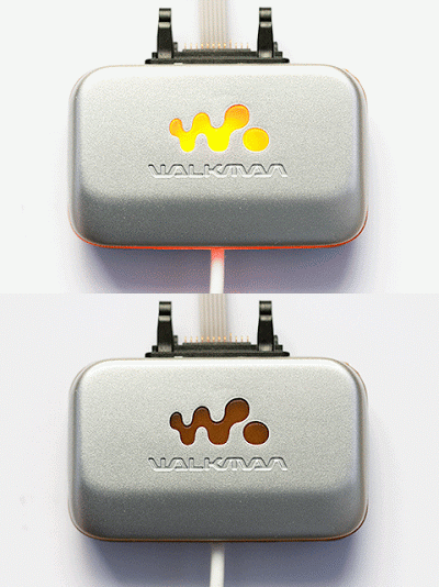
MMR-70 has an LED, but it's connected to Mega32 pin 16, so a bit of high precision soldering is required :) To control the LED we need to solder wire directly to the LED or close to Mega32 pin 16:
Using high temperature isolation tape you can mask the control point close to pin 16 and then easily solder a wire to it.
As usual, to protect RPi GPIO, a transistor is used as a buffer to power on the LED:
Now we can flash he LED every other RDS refresh cycle (one cycle - 80 RDS frames):
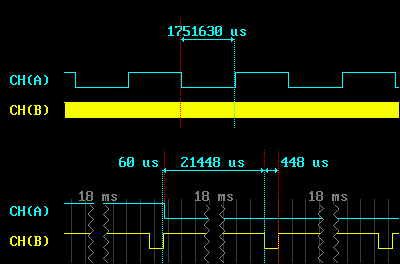
This is how it looks with a logic analyser:
Channel A - LED flashing, Channel B - RDS interrupts requesting next frame to be transmitted. So it takes 0.5 ms to process a frame request, then MMR-70 transmits this frame ~21.5 ms.
Links:
FMBerry on GitHub
MMR-70 discussion on www.mikrocontroller.net
Note: even without the LED lit up MMR-70 could take up to 27mA, which is a half of recommended RPi's load for 3.3V supply. With the LED turned on consumption rises to 36mA, so make sure you are not overloading your RPi if you have other devices connected to 3.3V. For my radio I'm going to solder TS2950-33 voltage regulator to MMR-70 testpoints to be able to use RPi 5V supply and connect MMR-70 to I2C bus 0 on P5 so it will not directly connect to RPI's 3.3V.


没有评论:
发表评论