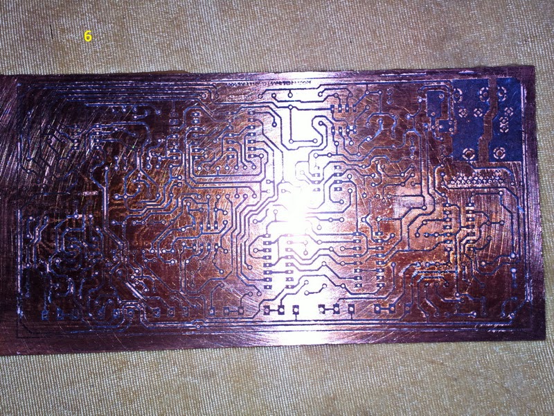
Solar Charger
Below is the simple Solar charger made from Desi UPS kit available in the market , where in normal condition if AC power given to UPS circuit it will start charging after 2 or 3 seconds,
it is more reliable , you can adjust charging setting .
this circuit will not work if it is connected to the battery you have to do some trick to activate the circuit , for this simply short both pc817 pins 3 & 4 , circuit will be activated when connected to battery.
both relay are kept parallel for maximum load , for this disconnect PCB line of big relay pin # 2 connect it to the small relay pin # 3 , because small relay will operated for the charging
Can be easily installed in the UPS box beside the other UPS card ,

it is more reliable , you can adjust charging setting .
this circuit will not work if it is connected to the battery you have to do some trick to activate the circuit , for this simply short both pc817 pins 3 & 4 , circuit will be activated when connected to battery.
both relay are kept parallel for maximum load , for this disconnect PCB line of big relay pin # 2 connect it to the small relay pin # 3 , because small relay will operated for the charging
Use both green wires in series with Solar plates
use 30 Amps relay instead of small relay both relays 30x2 =60 apms
Can be easily installed in the UPS box beside the other UPS card ,
You can simply call it hybrid power UPS System

Tuesday, 28 April 2015


Sunday, 22 March 2015


sound activated switch circuit ON/OFF
Here is a simple sound activated circuit
Best use :
assemble this circuit connect it with your mobile phone ring output ,
save a continuous tone (beep) in your mobile , set this tone for specific contacts (family members)
now assemble it with your house main gate lock ,
keep your mobile in silence profile just set continuous beep for specific family members
by calling the mobile output will be appear from mobile ring output it will trigger the relay
this relay will drive another relay it will trigger the lock on
Only known contacts will access the main gate other unknown will not be entertained where there will be no output if unknown will call.
lock will be remain open while ringing continues.


http://obaidkakar.blogspot.com/
Tuesday, 28 October 2014


Saturday, 4 October 2014

ON/OFF Switch GSM based (DTMF)
Below is a simple on/off switch using GSM mobile network .
It will work on miss call option , for which you don't have to pay
one miss call for ON and other for OFF .
due to the latching output from the decoder 8870 & 4028 IC , it is recommended to record two DTMF tone in mobile & set it as a ring tone for a specific user ,
It means that if we call the said mobile , lets i have set 2 DTMF tone 9 & 6 , output from IC 4028
pin # 5 which having # 9 DTMF tone is connected to opto-coupler PC817 then it is connected to IC 4013 ON/OFF switch ,
Once you call the mobile it will once activate (on) the pin # 9 while DTMF tone # 9 was set first , than after it tone # 6 will be observed at 8870 , so it will activate # 6 , pin # will be off ,
again by calling the the mobile circuit will be ready for the next action either off or on.
For confirmation a simple switch will be added to make call busy or continuous ringing which will confirm that the desire action ON or OFF successfully done.

PCB design in Eagle CAD

With addition of relay & LED , power taken from mobile battery

 http://obaidkakar.blogspot.com/
It will work on miss call option , for which you don't have to pay
one miss call for ON and other for OFF .
due to the latching output from the decoder 8870 & 4028 IC , it is recommended to record two DTMF tone in mobile & set it as a ring tone for a specific user ,
It means that if we call the said mobile , lets i have set 2 DTMF tone 9 & 6 , output from IC 4028
pin # 5 which having # 9 DTMF tone is connected to opto-coupler PC817 then it is connected to IC 4013 ON/OFF switch ,
Once you call the mobile it will once activate (on) the pin # 9 while DTMF tone # 9 was set first , than after it tone # 6 will be observed at 8870 , so it will activate # 6 , pin # will be off ,
again by calling the the mobile circuit will be ready for the next action either off or on.
For confirmation a simple switch will be added to make call busy or continuous ringing which will confirm that the desire action ON or OFF successfully done.
PCB design in Eagle CAD
Tuesday, 29 April 2014
CAR TRACKER (GSM + GPS)
Features:-
1):- Get location all over Pakistan with Google Map
2):- Alert while someone nearby Car.
3):- Full control using DTMF remote control.
4):- Only specific users can access control.
5):- Engine Kill release option
In this project Nokia phone NOKIA C5 were used,
1):- In this project a phone set required having built-in GPS module where you can get location coordinates and GSM location through sms from your vehicle
2):- There will be call originated from car while someone try to open car door.


You can get alert from car while someone try to open car door.
For call originating from car will required speed dial option in mobile phone set.
First enable speed dial option, save your number with specific digit , solder the desire button, now both wires from the will be interface with car doors switch,
It means that if someone open the door switch will be operated resulting to dial the specific speed dial number.
Basic concept in circuit is that despite of different cellular mobile phone number in the tracking car should pass a combination (sequence) lock key, for this a simple 4081 AND gate IC were used where 4 keys required in a desire sequence, these 4 inputs were taken from 4028 (4 bit binary to decimal converter) IC to 4081, which is directly connected to 8870 DTMF IC outputs, in the last a simple touch on/off circuit were used from IC 4013.
Interface between ICs 4028 & 4081 were done with the opt coupler PC817,
Once sequence completed in IC4081, reset will required it is then done while using relay 2 along PC817
FM Transmitter ( 88- 108 MHZ ) from Car MP3 player 6 Watts
Below is the versatile FM Transmitter build around car MP3 player ,which can deliver up to 6 Watts.
In this circuit RF signal is taken from a MP3 player built-in low power transmitter , it is than boosted by the two more RF stages ,
For making any RF transmitter circuit at least two meters are very necessary , one is frequency counter & the other is RF field strength meter.
In the first stage of transmitter one of the best driver transistor 2SC2053 were used .you can use the other transistor up to 500MW power for this stage. In the second stage another RF transistor 2SC1971 were used.also you can use any equivalent transistor.
Note : L3 will be 4 turns , L6 will be 12 turns, Heat Sink required for C1971 (C2053 can be used ).

Use fix 20 PF capacitor instead of variable capacitors (30 PF)


In this circuit RF signal is taken from a MP3 player built-in low power transmitter , it is than boosted by the two more RF stages ,
For making any RF transmitter circuit at least two meters are very necessary , one is frequency counter & the other is RF field strength meter.
In the first stage of transmitter one of the best driver transistor 2SC2053 were used .you can use the other transistor up to 500MW power for this stage. In the second stage another RF transistor 2SC1971 were used.also you can use any equivalent transistor.
Note : L3 will be 4 turns , L6 will be 12 turns, Heat Sink required for C1971 (C2053 can be used ).
Use fix 20 PF capacitor instead of variable capacitors (30 PF)
Simple field strength meter circuit
Surah Al-Kahf (The Cave) By Mishary Rashid Alafasy .
Cave of Ashabe-Kahf (exterior)
This is regarded as the cave in which a group of pious youths (equated with the Christian legend of the ‘Sleepers of Ephesus’) sought refuge from a tyrannical pagan king and in which Allah (Glorified and Exalted is He) caused them to sleep for 300 years. Their story is mentioned in the Holy Quran in Surah Kahf. The cave is located in the suburb of Abu Alanda in Amman.In around 250 CE there ruled a Roman king called Daqyanoos (Decius) who would annually hold a gathering dedicated to the worshipping of idols. Many people would attend, dressed in their best clothing. However, one youth believed in the oneness of Allah (Glorified and Exalted is He), the teachings of Isa (upon him be peace) and shunned pagan worship. He rebelled against the practices that were happening in the society. He attracted another youth and then another to form a small group.When the king heard of their rebellion he became very angry and issued a command for them to be killed. In order to save their iman (faith) they fled and went into hiding. On their escape route they met a young farmer who owned a dog; they gave him da’wah, he accepted and decided to also join them. Eventually they came to a cave in which they made dua to Allah (Glorified and Exalted is He) for ease. They decided to take rest there for a while, leaving the dog (named Qitmir) near the entrance as a guard. Allah (Glorified and Exalted is He) caused them and the dog to sleep for 300 years.Allah (Glorified and Exalted is He) describes their sleeping in the Holy Quran in Surah Kahf:“And thou wouldst have deemed them waking though they were asleep, and we caused them to turn over to the right and the left, and their dog stretching out his paws on the threshold. If thou hadst observed them closely thou hadst assuredly turned away from them in flight, and hadst been filled with awe of them.” [18:18]The Quran further states that the period of time these sleepers spent in the cave was 300 years during which the calendar of their people was changed from solar to lunar and, as a result, the period of their sleep was 309 years. When they woke up, they had no idea they slept for centuries and thought they had only slept a few hours. When they sent one of them to buy food, the shopkeeper was amazed to see such old coins and the reality of the time they had spent in the cave gradually came to light. The present ruling king, whom some scholars have identified as Tandoosees, was a believer who came on foot to see them and seek their blessings. When these young men died they were buried in the cave along with their dog. The bones of these youth and the dog are visible to see inside.Apart from Amman in Jordan, the location of the cave is also claimed to be in Turkey. And Allah (Glorified and Exalted is He) knows best.To the left of the entrance is an ancient olive tree. At one time a small church was built on top of the cave; this was converted to a mosque with the mihrah still being visible above the entrance.
http://equranplayer.com/mp3-quran/reciter/mishary-rashid-alafasy/1062/018-al-kahf-the-cave.html
This is a versatile & secure circuit for any home, whole circuits is explain of my post
DTMF Remote Control GSMBased
In this project you will need a mobile phone where you can set your own ring tone,
Then you have to record any DTMF tone , lets record number 3 tone in mobile direct or by PC , transfer this tone to the mobile ( circuit Mobile) ,
Now set this tone as a ring against all the family member stored in mobile,
It means that if any family member will call the mobile DTMF tone of # 3 will heard from mobile ,
Now this mobile is connected with circuits (DTMF Remote Control GSMBased),
All process is same like my post (DTMF Remote Control GSMBased),
But in this condition due to the same tone from all the family mobiles will be the same output ( tone) from the BCD 4028, like Tone 3 will be taken from pin 15 of 4028.
Other caller will not be entertained having no any assigned DTMF tone,
Note : This circuits can be connected with main gate lock , where only family can access .


Monday, 25 November 2013
Day Night Switch (Solid State)
Now a days LED lights are so common everywhere, you can direct connect it with battery no need any UPS / invertor, I decided to installed such power LED light at roof top along day night switch, so I design a simple switch circuit with minimum components, I found it very reliable & stable, a high power FET were used, you don’t worry about the FET you can use any powerful N-Channel FET available in the market which are mostly used in UPS. Heat sink must , insulator Recommended between FET & heat sink if not no issue .
I used FET 47N60C3 -MOSFET , LDR, Variable resistor 305 mega ohms, Pressure 12 V.
Separate heat sinks for both FET & LED are recommended.
http://pk.linkedin.com/pub/obaidullah-khan-kakar/44/823/975


Separate heat sinks for both FET & LED are recommended.
http://pk.linkedin.com/pub/obaidullah-khan-kakar/44/823/975


Monday, 23 September 2013
DELTA PULSE 3 METAL DETECTOR
Delta Pulse 3 metal detector (Pulse induction) is a versatile & professional detector, same like delta pulse 2,
This detector have a LCD screen facility, but my this project is under construction, where I have already build delta pulse 2, you can find it on youtube ,
http://obaidkakar.blogspot.com/2015/04/delta-pulse-metal-detector.html

DTMF Remote Control GSM Based
Below circuit is consist of DTMF decoder IC 8870 & 4 bit BCD to decimal 4028 IC,

Four binary outputs are connected to the inputs of BCD to decimal 4028 IC
You can control up to 9 appliances by this circuit, out puts will be in latched form,
Mobile phone can be easily used with circuits, all the keypad button 1 to 9 will be used.


 http://obaidkakar.blogspot.com/
Friday, 12 July 2013
PTCL EVO Wingle 9.1 Mb USB (Built-in Wi-Fi) powered by mobile battery (like a portable 3G EVO Nitro Cloud)
Actually this a very simple project where EVO Wingle 9.1 Mb is powered by mobile battery including charging facility plus indication LED & an on/off switch, backup time up 3 hrs. Depending on battery Amps,
Where i used LG battery 1350 MA battery


It can be easily charge by using common Nokia charger, don’t worry about over charging there is built in cutoff circuit in side every mobile battery,
One thing I missed that there should be USB pin charging facility and schematic of this project, no issue I will add it soon.
http://obaidkakar.blogspot.com/
Tuesday, 11 June 2013
ON/OFF Switch using DPDT relay (220V) & PC mouse
In this circuit no such electronic circuits used only one relay & PC mouse were used, this is very simple circuit, here 2 micro switch & 8 pin DPDT relay 220 v used, if you see the connections of the relay you will see that main AC 220 were connected to points 7 & 8, another wire taken from pin 6 to pin 2 through micro switch (OFF), 2 wires were taken from pins 8 & 2 to the micro switch (ON),
Device to be controlled wires are taken from pins 3 & 1.
In the presence of 220 AC if we press ON switch relay will energize while current flow through pin 7 & 2, where current will flow through switch from pin 8 to pin 2 , both 7 & 2 pins are the rely energizing points ,
when relay energized it will remain energize due to pin 8 & 6 to pin 2 through micro switch ( OFF ) , because current will flow from pin 8 to pin 6 ( now connected due to relay energized ) .
By pressing switch OFF supply will be disconnected between pin 6 & 2, relay will become in normal condition
https://plus.google.com/photos/109894115660040034374/albums/5888296058657761297/5888296058072101826?pid=5888296058072101826&oid=109894115660040034374-------------------------------------------------------------------------------------------


Tuesday, 4 June 2013
Auto Changeover from Inverter / Generator to Mains Supply
Below is the Inverter & mains change over circuit, in this circuit both Inverter supply & mains supply combined which is called UPS , for this purpose 8 pin DPDT relay (220 V ) were used as explain in the diagram ,
Blue wires are for Inverter ON & OFF switch, in absence of MAINS supply Inverter will be in ON condition (pin 1 connected to 4), as can be see in diagram,
One of the wire from mains, Inverter & output are kept common,
Pin # 8 is common for 5 & 6 pin, where main connected to pin 6 & Inverter to pin 5.
Green wires to pins 2 & 7 are relay energizing points, where both wires are connected to the mains,
In absence of mains Inverter will be in on condition due to pin 1 & 4 connected, supply from
Will be available due to pins 5 & 8 connected each other,
In the other hand if mains supply came relay will be energize due to pins 2 & 7 , pins 6 will connect to 8,
Pin 1 will be disconnected from 4, Inverter will be off.
You use generator instead of Inverter but the Technic is same
Keep in mind that one wire from mains supply , invertor & output must common

hello
回复删除please send me you email address
i want to make order
regards
p_niceboy3@yahoo.com